-
×
 Uber- Switch V1.1 - Relay True Bypass with mute - KIT 1 × $ 9.10
Knowledgebase
Switching: Relay True-Bypass – Circuits using a microcontroller
01
Aug
Aug
What is a microcontroller?
A microcontroller is a device that can be programmed using a programming language (like C) and has a wide variety of input/output ports (pins). Those ports can be input and detect the state of switches (On/Off), read analog voltage or they can be output and set ports to On/Off, give out analog voltages and everything you can imagine. It is used in your washing machine or your car to control the engine.
Is using a microcontroller for switching a relay not overkill?
NO. Microcontrollers come in many different variations, sizes and have different abilities. The smalles and most basic ones are just about right to do the job. Usually small PIC microcontrollers (from Microchip) or ATtiny (from Atmel) are used.

How does it work?
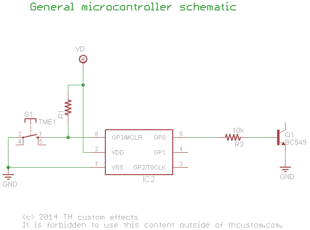
In the above schematic you see a general microcontroller application to control a relay. The microcontroller needs a regulated power supply (5V in this application).
GP3 is set as input and allows the microcontroller to read the status of the momentary switch. GP0 is set to output to control the transistor. It is Low (0V) when Off and High (5V) when On.
R1 is pulling the input to High-level (5V) when the switch is not pressed. Once the switch is pressed the input goes to Low-level(0V) until the switch is released.
What happens inside the microcontroller?
The microcontroller is programmed to continously read the input of port GP3 and will toggle the output GP0 accordingly.
But what about switch bouncing?
We know that mechanical switches always have switch-bouncing. So why should a microcontroller be not be affected by this? Indeed it is affected by switch-bouncing. But we can program it in a way to eliminate these bad effects by using a proper algorithm to suppress these signals. Good programmed microcontrolles are very reliable and almost impervious to it. But be warned that there are cheap momentary switches on the sale that have such bad switching characteristics even a programmed device cannot make it a good one.
Now to the fancy stuff:
In the above schematic you see that there are unused pins on the microcontroller. What can we do with them? A lot of fancy and usefull things!
Adding a remote control to your effect
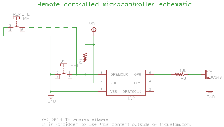
All we have done in the schematic above is to add another momentary switch parallel to the first one. It can easily be wired external by using a Jack and some standard cable. To make this professional additional RF protection should be added to the remote jack. But it will work without problems on short distances of a few meters.
Two channel switch using a single microcontroller
First we can use the two pins to do another pair of input/output and have two momentary switches driving two separate relays using a single microcontroller.
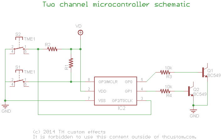
How does it work?
This works absolutely the same as the single channel version but makes better use of the microcontrollers ports. You could have Channel1 as True-Bypass and Channel2 switch the Lead-Channel or something.
Chained Switches
Another thing that can be done is to make use of a port to chain devices together. One thing I used this for is to build switches that act like radiobuttons. (If you have multiple switches in a radiobutton style this means that only one switch can be On at any time. If a switch is pressed it goes On and all other switches are turned Off.)
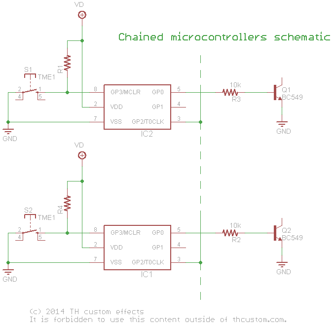
How does it work?
We have multiple devices of the same type which are connected by an extra wire which works as a signaling bus. If a switch is pressed the corresponding microcontroller sends out a signal to all other devices telling them to go into the Off state.
The Mute-Before-Switch True-Bypass version
We can also use the extra ports to control additional parts in the circuit which do something special. In this case the output signal is muted just before the relay is switched Off to prevent any popping noise caused by this. (See article on “Popp”)
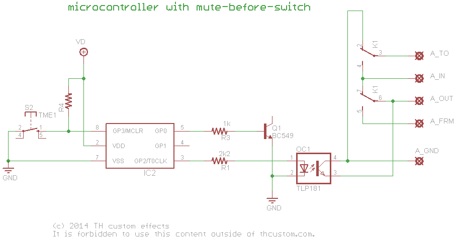
How does it work?
In the above schematic we have added an optocoupler that can switch the effects output to Ground.
If the microcontroller is about to switch the relay Off it will first switch on the optocoupler and after a very short period of time then switch the relay off. This causes the effect to be muted before the switching which should prevent any popping noise. When the relay is switched off the optocoupler will be deactivated as it has done its task.
Pingback: Relay bypass : mise au point et fonctionnement - Coda Effects
Pingback: Relay Bypass: conception and relay bypass code - Coda Effects
Pingback: Sistema de enrutamiento de efectos de guitarra (Looper de efectos programable) - biuvit