DIY, Modular Controller
The 10-loop modular controller build report – chapter II
Since we have already built the audio switching part in the first chapter, we now do the microcontroller.
In the beginning of the project there were several options on the display that can be used but due to the restricted time at hand the version with the OLED display most complete. They come in 1.3″ and 0.96″ size where the 1.3″ one is used in this build.
Building the control and display units.
The control units do not really need special soldering skills but you need to have some endurance to make all those solder joints.
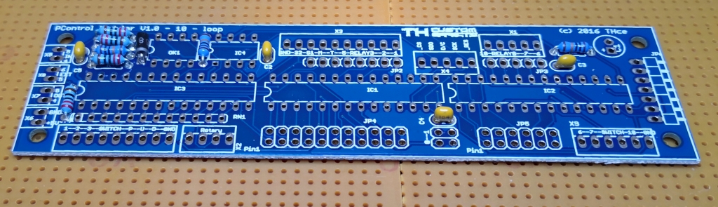
Again starting with the lower height parts first, then sockets for the ICs
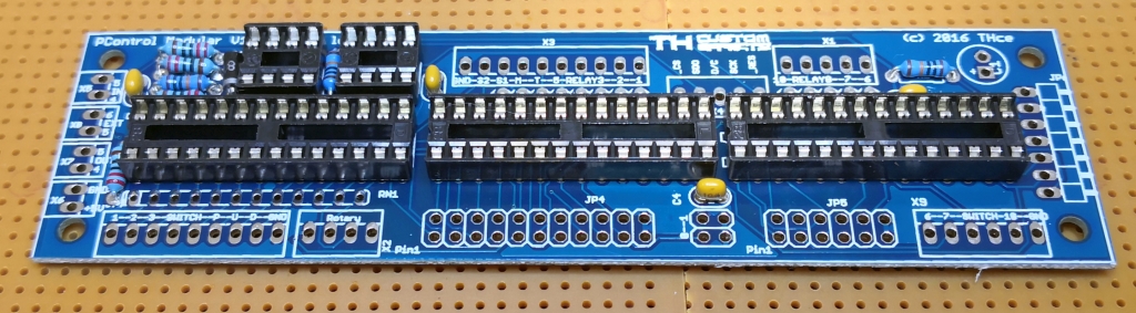
and the connectors go last

It is highly recommended to use connectors at least on the controller board as there will be a lot of wiring which will be cumbersome if soldered directly to the board. In addition ribbon wire is used to minimize frustration 🙂
Again there is a 3D printed piece (grey plastic in below picture) that helps fitting the controller board and the power supply. It is highly recommended to use it as it keeps the boards where they belong without the need to drill holes and use spacers to put the boards in.

We did a lot of testing how and if the digital logic generates noise or otherwise affects sound but we found no shielding was neccessary. Still, if you want, you can put a small grounded copper board between the controller board and the audio boards. There is a slot in the plastic just for this.
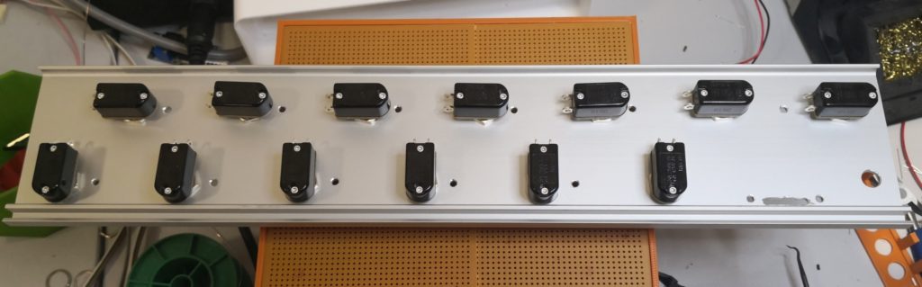
Footswitches and Indicators
A lot of the wiring is caused by the footswitches and the corresponding LED indicators next to them. There are indicators on the control boards that can be used which allow LEDs to be mounted on the backside which can stick through the enclosure lid close to the backside of the unit. If used this reduces wiring a lot. But we did decide against it and used bicolor LEDs next to the footswitches to indicate active loop and selected patch.
As you can see – lots of drilling for the footswitches and LEDs. At the right hand side you can see a small slot for the OLED display and some mounting holes. Next to it is the hole for the rotary encoder which is used to easily dial in more complex things in the menu and during programming.
Here with LEDs:


And again to reduce wiring the pins of the LEDs are used to make the ground connection and give extra hold for the LED. CLR (resistors) for the LEDs are required as well. After that the LEDs are put into place using hot glue 🙂 Not my favourite but working well for a prototype.

Here you see the ground wiring and the first set of switch cables connected.
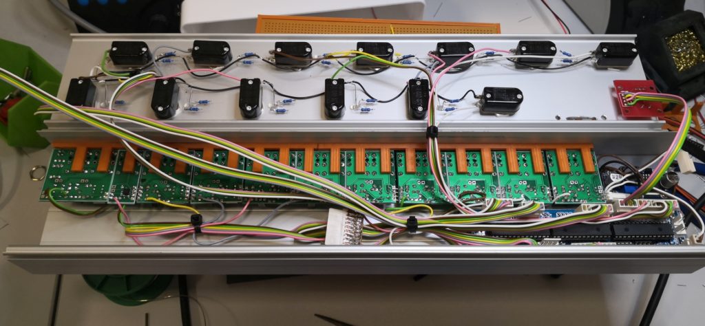
Due to the fact that the relay connectors go directly to the switchboards I had to break them up and use a connector to also use the same signal for the LED indicator.
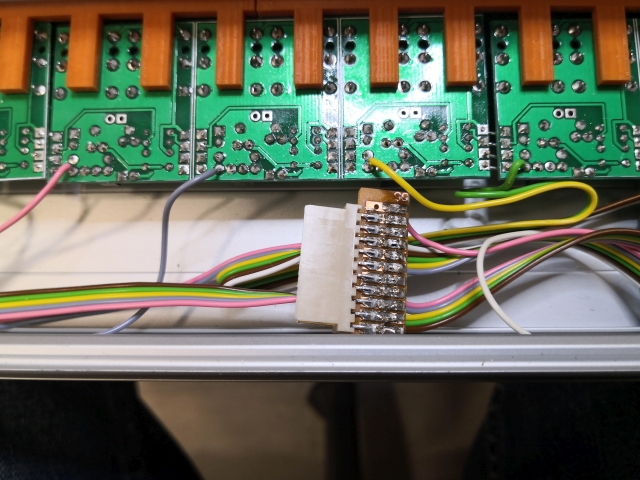
All resistor leads have been sealed using heat shrink and a hot air gun to tighten it.
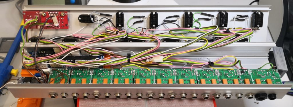
And here is the picture of the completed wiring:
Detail: Wiring and mounting the OLED and rotary switch
The OLED/rotary switch board has been cut into two as we found that the OLED board had to be more close to the top lid than possible if the rotary switch is mounted on the same board. You can see appx. 2mm difference in height in the picture below. Metal spacers and nuts are used to hold the display in place.
Due to space restrictions we used a 90deg jack for supplying power and the interface wires are directly soldered to the board with a jack to the control board at the other side.
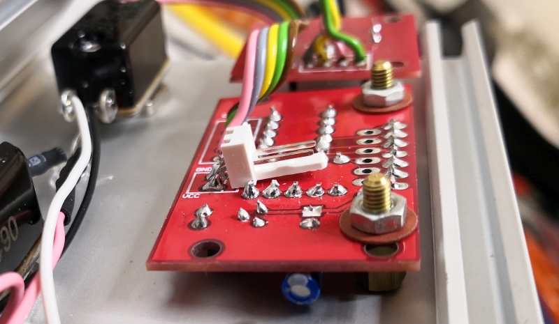
On the top we have used a 3D printed piece that tightly fits the display and provides isolation from the backside to the lid. An acrylic top is still missing here on the picture but it will be mounted using the same screws keeping the whole unit secure and protected in place.

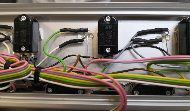
Detail: Marriage of analog and digital ground
One of the most impotant things to reduce noise and guarrantee superior signal quality is the correct grounding of the unit and the connecting of digital and analog ground.
The unit is powered by an inexpensie but very good DC-DC brick you can get for USD 4.00 from China, delivering +5V @ 1.5A without problems in a very small space.
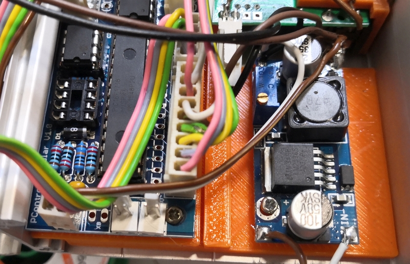
As can be seen here we have used one of the brown ground wires that is connected to the supply of the audio switching bus and connected it to the analog ground directly at the input jack. Further a tinned blank end of the wire is securely pressed to the enclosure directly behind the jack using the jack nut to press it tight.

Awesome!!!! I’ve been waiting for this. Checking this place every few months hoping for updates, this made my week. So great!!!
Cannot wait I’d love to be able to preporder or que up or something to make sure to get some of the first batch of boards. A 10 base and two 5 extenders plus oled. (if your going to supply that too)
This is exciting to me. Just started the V1 looper but number II looks very electronical :))
Thanks
Manny