DIY, Modular Controller
The 10-loop modular controller build report – chapter I
It started as an improved version of the EPIC Looper and due to serious time restictions it could not be brought to an end 4 years ago.
Recently things changed and we revisited the project and found it still an unmatched and high-end DIY project for every experienced builder.
It took two month to build the here shown prototype due to fixing some minor mistakes and prooving to fit it in the enclosure we decided to use.
Have fun looking at it. Parts to build your own version of the modular controller will be available shortly.
Please check the link regularly to get all the comming updates.
The first steps
Very important is the choice which enclosure to use. We got one four years ago and it is still available at musikding.de: https://www.musikding.de/Looper-enclosure-40cm
Here is the first idea how we would set it up.
Then we did make the main decision: What is it that will be switched with the controller? As it is a modular concept there is a range of possibilities:
- Standard audio loop SEND/RETURN
- Standard IN or TUNER/IN
- Mutable OUT
- Two-Amp OUT A/B switch
- Amp pedal switcher (switches channels in the amp via its footswitch connection)
We decided to go with the following:
- TUNER/IN
- 8 Standard Loops SEND/RETURN
- Mutable OUT
- 2 Channel Amp pedal switcher
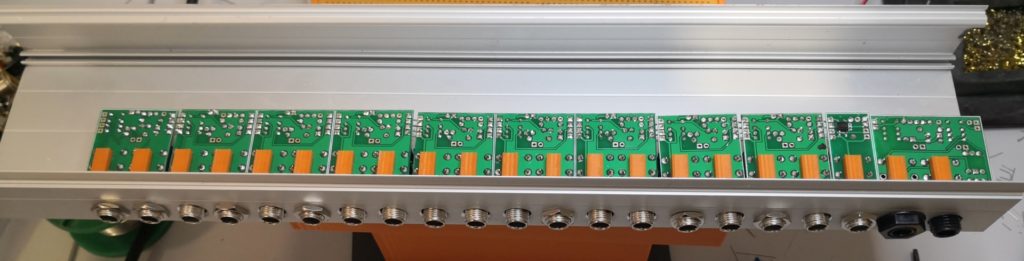
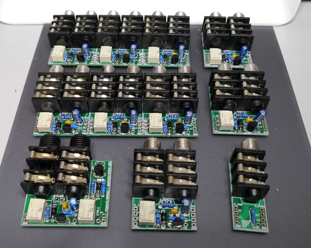
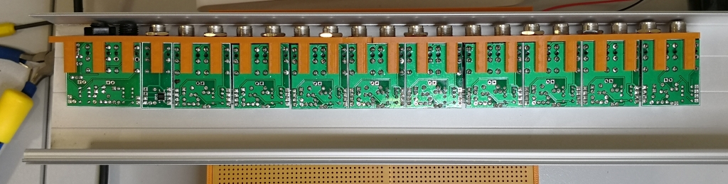
You can see those boards here from right to left (green). The display board overlaps but we had high hopes it would work out 🙂
Audio boards assembly
lets start with populating the switchboards:
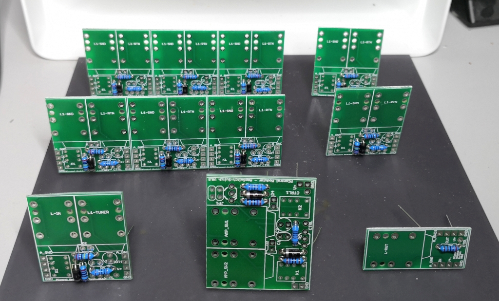
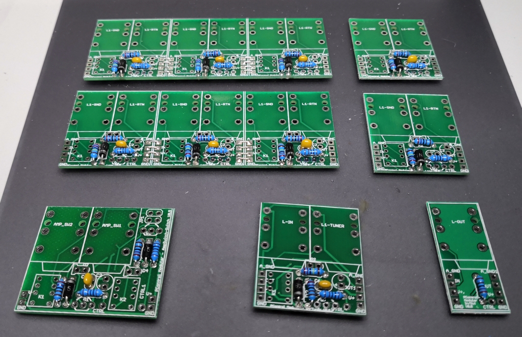
Low height components first, then higher components:
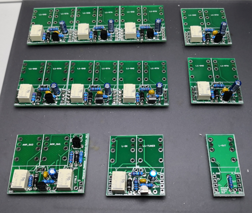
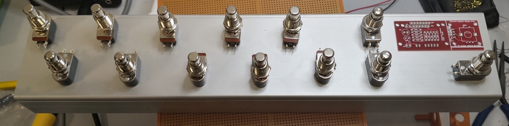
And finally the jacks:
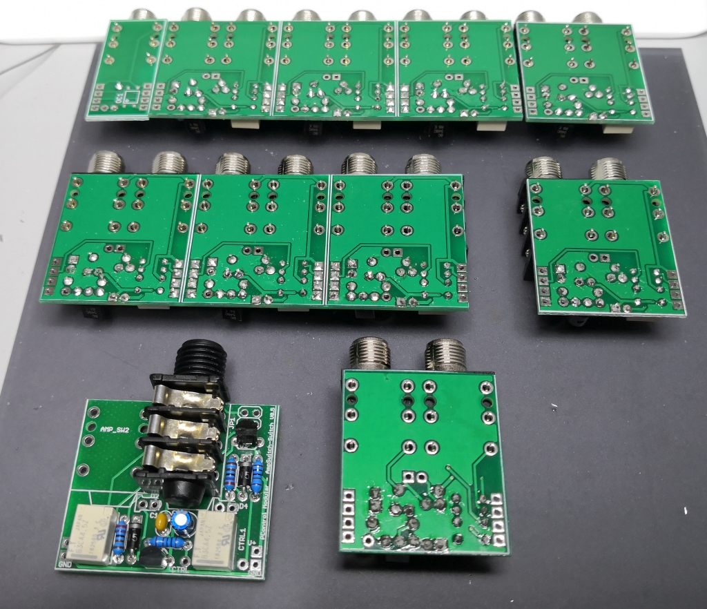
The boards have connectors at the side which make up a bus system for the audio signals and power rails. They need to be connected.
Dont throw away the cut off leads of the parts from populating the boards because you need them now. You can also use silver gauge wire but thats not really needed.
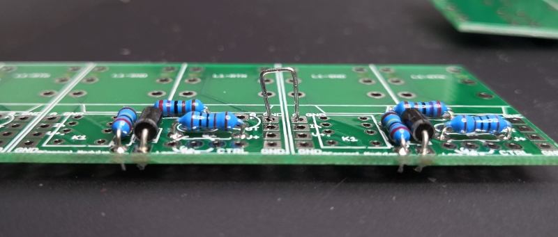
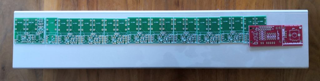
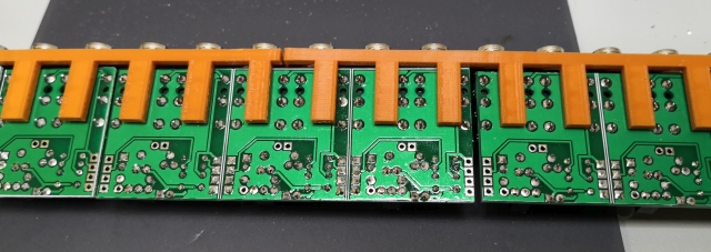
Above picture shows the wiring of a 3-loop board. The connection of the boards themselves you do when they are all populated. To help with the wiring we made some 3D printed helpers that also can stay when mounting the jacks into the enclosure:
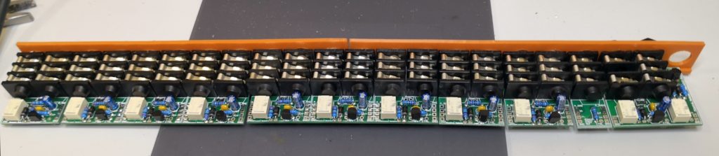
This makes connecting the boards to each other super easy and you take the whole thing and put it into the enclosure when you have drilled the holes.
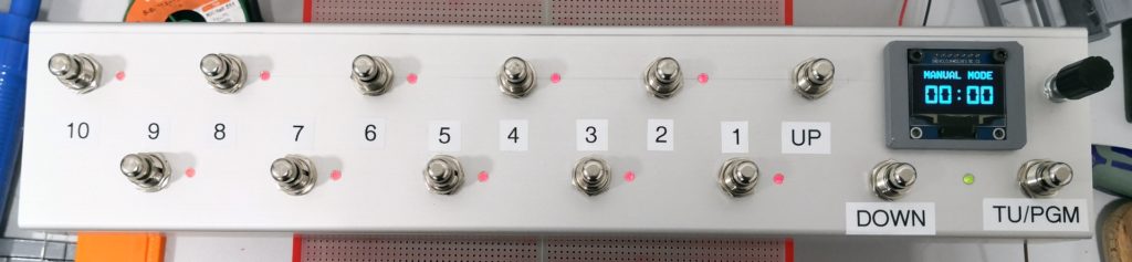
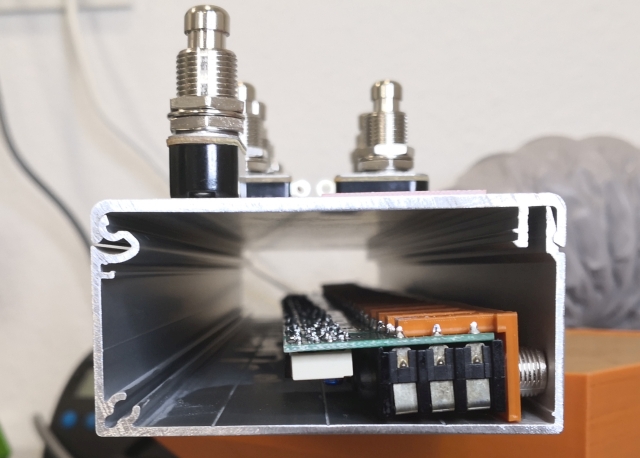
The next picture shows how the jacks fit into the enclosure:
And yes, its mounted upside down to have the switches go from right to left as usual.
When mounted the first part is completed: