Knowledgebase
Switching: Relay True-Bypass – Circuit Overview
01
Aug
Aug
There are a lot of different circuits out there which can control relays. I will focus on the ones I am aware that are used in the control of musical effects.
I will try to give an overview of the different circuits I know and explain how they work.
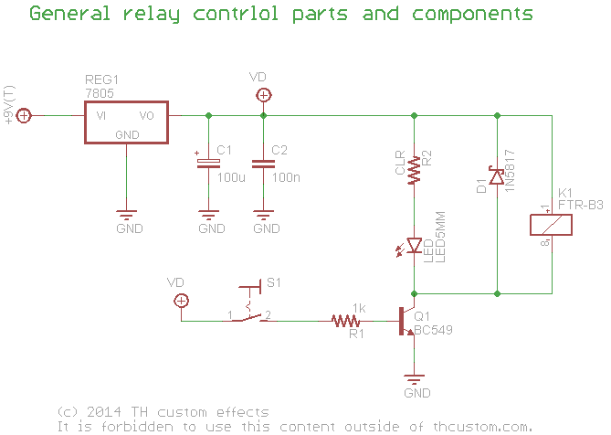
Common control parts and components needed
What is common with all relay control circuits is that they need to send out a signal to the relay which has two states: On and Off. Also the relay needs a stabilized power source to work.

The above circuit uses a standard 7805 voltage regulator to generate a stabilized 5V supply for the relay. The relay can be of a 4.5V or 5V type in this application. Both will work. Please note that this is about non-latched relays only!
The ON/Off signal is very simple generated by a latching 1 pole switch connected to the relays positive power rail. Once it is switched on the transistor conducts activating the relay and indicator LED as described before.
So, we have a relay and a mechanical single pole switch. Is this better than just using a 3PDT stomp switch?
The answer is: Yes, because you now can use a smaller SPDT switch which gets you more quality for the same price as a 3PDT. It will make less noise and has an enhanced lifespan compared to the 3PDT switch.
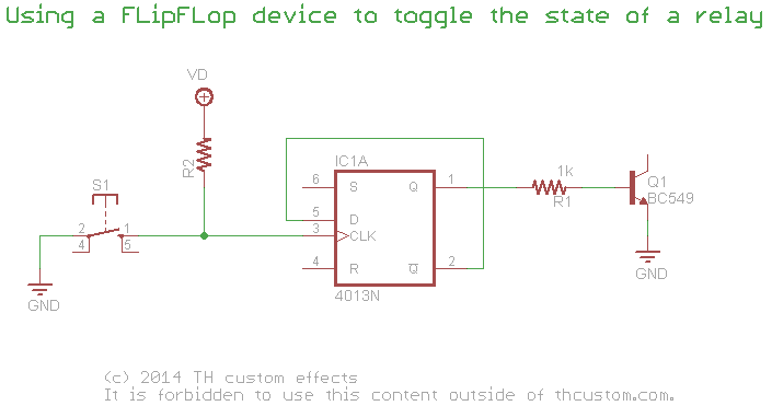
Using momentary sitches to control the relay
You may want to use momentary switches to control your effects unit. Maybe because it is rack mounted and you want to press it by hand, Maybe because you want to control it remotely or for many different other reasons you can imagine.
But how do you accomplish the task to toggle the state of the relay using a momentary switch? Replacing the latched switch from above with a momentary type does not really work. The relay would only be active as long as you press the switch – which somehow will hinder you to do your job on stage – like playing the guitar 🙂
So we need a circuit that allows to toggle the state of the relay with a momantary impulse from your switch. A good general circuit would be a D-type flipflop circuit which triggers on the negative impulse of the clock signal (CLK). The state of output Q changes with every impulse from the clock signal.
Would it really be so easy? NO! The main problem you face is that all mechanical switches have switch bouncing- meaning that while the mechanical contact closes there are small spikes in the signal until the contact finaly closes/opens which will trigger your flipflop and thus render the circuit useless.
To overcome the switch bouncing issue there are many different solutions, but all of them deal with time. The key to success is to somehow delay the signal of the switch until finally the contact is made and the switch bouncing is over.
Those solutions can be easily categorized into two general types. Those which make use of a microcontroller and others that dont.