Knowledgebase
Equalizers: Parametric EQ vs. Graphic EQ
Graphic EQs
Graphic EQs are named so because of the fact that every frequency band is represented by a linear potentiometer and they are aligned next to each other.
Looking at all sliders at once you see how the frequency attenuation and amplification looks like over the whole band.
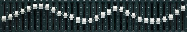
5 band Graphic EQ

Parametric EQs
On the other side you may just dont want to use a graphic EQ because you have special requirements like these:
- manipulating the corner frequency of a band
- adjusting Q (the quality)
where usually the corner frequency (i.e. 700Hz) can be set in a range (like 400Hz and 1400Hz) and Q (the width of the band – meaning frequency range effected) between 1/12 octave to 4 octaves.
A Q of 20 will mean 1/12 octave in frequency range. You could boost or attenuate single notes with this. So, this is only for very special tasks.
A Q of 0.6 is 3 octaves and therefore a quite wide range being manipulated.
Useful Q ranges from 2 to 5 in standard environments.
There are two philosophies with param EQs. The first one – lets call it “set and forget” uses internal trimpots to define the corner frequency and Q. Only the level pots are accessible. This is usually used in a fixed setup.
The other is “full control” meaning all parameters can be dialed in via pots from the front side. This is very comfortable in a flexible environment but there is a chance that you will never be able to dial in a specific setting you did like again after working on something else 🙂
Parametric EQs usually are made from gyrator circuits. There is a version with transistors and one with OpAmps.
A calculator for the corner frequencies and Q can be found here: http://www.muzique.com/lab/gyrator.htm
3 band parametric EQ with trimmers

1 band parametric EQ with trimmers
