Development
PControl Modular Part #5

11
May
May
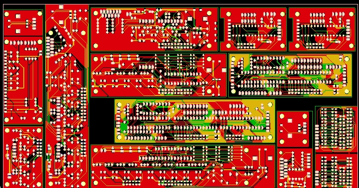
As said last time I’ve done new layouts for almost all PCBs because of the need to use a different processor. Also I did a lot of thinking about how the boards will be connected to switches, relays etc. A new connector and a distribution board has come out of this idea.
New PCBs !
This is what was ordered:
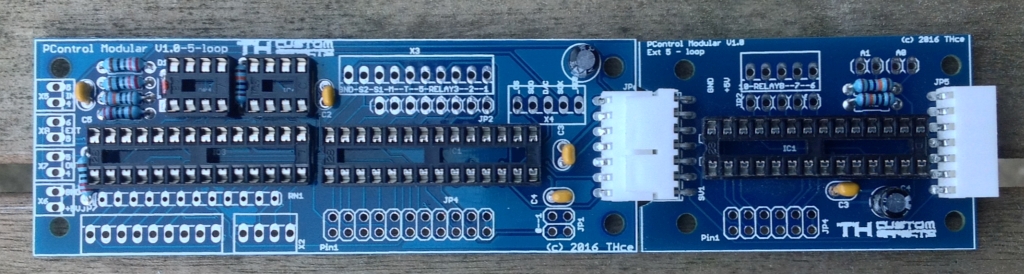
This is what was received:
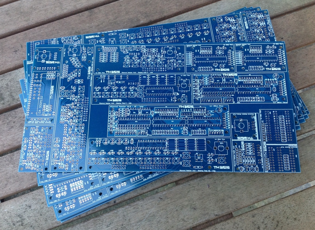
Looks good so far 🙂
5-loop controller, 7-segment piggy-board and OLED piggy-board
Unfortunately I made a mistake and they wont fit together. I need to redo both display-boards 🙁
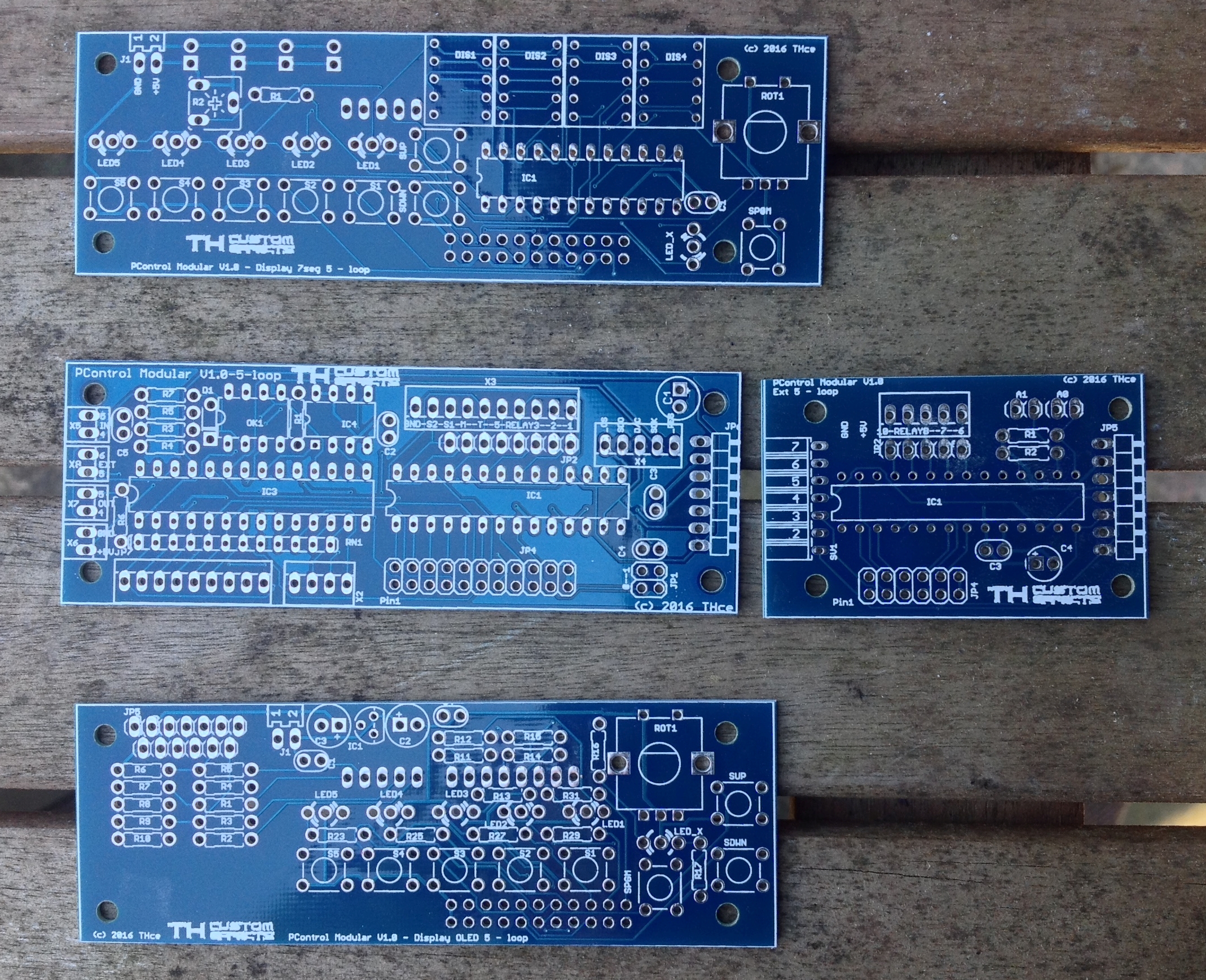
10-loop controller, 7-segment piggy-board and OLED piggy-board

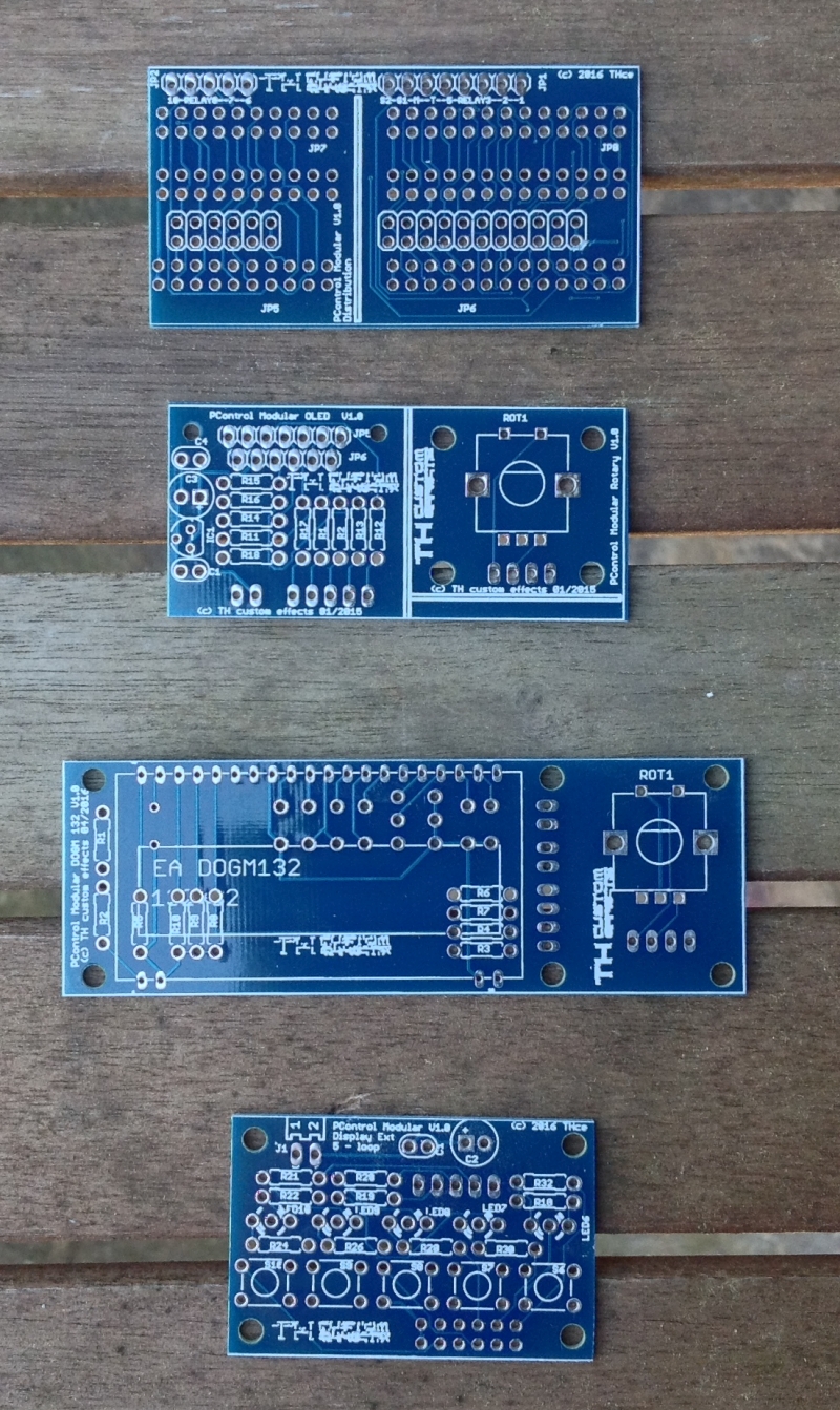
Helper Boards (Distribution-Board, Display-Boards [LCD, OLED – each with rotary encoder], 5-loop piggy extension
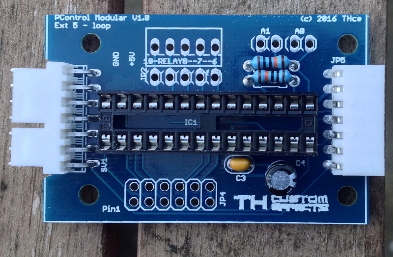
Populating the boards
There are not really a lot of parts to be soldered.
5-loop controller and 5-loop extension board
10-loop Controller

5-loop extension board
Next step
is to build a prototype and amend the existing code to support the new processor.
I will go with a 10-loop controller with a piggyback OLED. Thats a good setup for programming/debugging as the OLED has space to display the debug information.
Also a more standard setup for a floorboard will be done to be able to start documentation.