Development, DIY, slideshow
PControl Modular – The next generation DIY looper
25
Nov
Nov
Since I have discontinued the PControl Looper I have received so many requests to as when the new PControl will be available that I cannot count them.
Here is the documentation of the development of the new device and my thoughts – based on a lot of feedback and wishes I have received since I offered the PControl to the DIY community.
PControl Modular
comming soon!
A very flexible design that can be adapted to the users need. Because its modular!
What does it mean?
The whole setup is based on the fact that every guitarist or bass player has individual thoughts about his pedalboards and how things should work together. So, why not offer a flexible solution he can configure to his needs?
The quest already starts with lots of questions: How many loops do I need? I want to change the order of effects in the signal chain. I need a stereo setup. I need a minimal solution that fits in a small enclosure. I need to feed my signal into multiple amps. I need to send MIDI changes to my Digital Delay. I want to control my Looper with a MIDI footswitch-board. I want the signal muted while effects are switched to avid popping noises. I need a Tuner Out jack. And a lot more!
This is what I have come up with so far:
Lets get down to the basics what a programmable looper can do:
- It is able store the users perferred settings in its memory
- It switches things on and off
- it offers a user interface (LEDs, Display, Buttons)
So, the first thing we can do is to design a control unit that allows to store settings and has the ability to switch things on and off. It should also be able to offer connections for switches and means of displaying information.
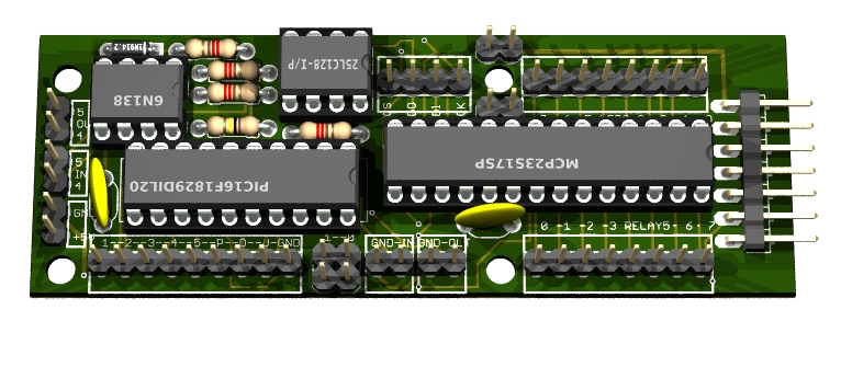
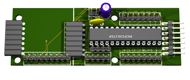
The main control unit:

You can say: That looks pretty technical, but where are the relays, where is my display and where are the switches?
Thats the point! Its modular and therefore you can choose which modules you are connecting to it.
This control module already can do a lot of things:
- controls five switching modules
- connects five loop switches and one programming/bank switch
- optional connects bank up, bank down and tuner-on switches
- connects LED indicators for five patches in a memory bank
- has MIDI In/Out
- has the ability to control the mute-function
- optional connects to advanced display and control modules
- connects to extension modules
Lets have a look at the planned switching modules first.
All modules have pads on the sides which need to be connected to provide power and the signal routing through all connected modules. Unfortunately the 3D renderer used does not have the onboard jacks in the library but you will get the idea.
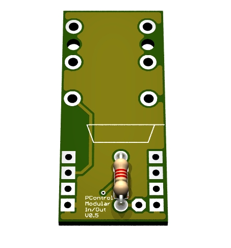
The Tuner/In module:
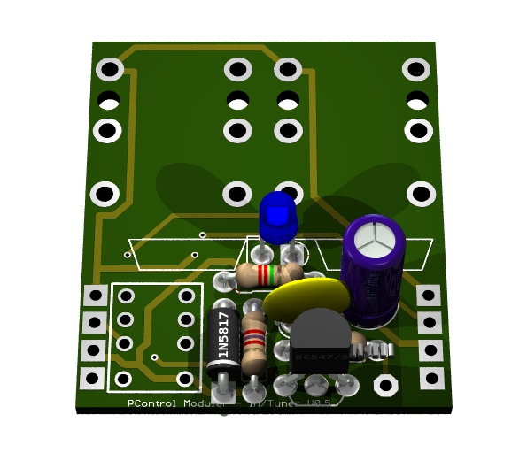
Contains the In-Jack and a Tuner-Out jack. If the (optional) Tuner-On-switch is pressed the signal is routed to Tuner-Out and the signal goes quite while you are able to tune your guitar.
The Loop-Switch:
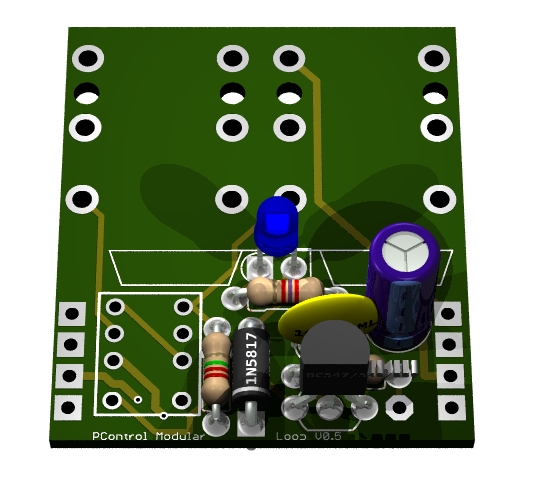
Provides Send and Return-jacks to be used with your pedal. The control unit will switch it On and Off based on your programmed settings or the corresponding footswitch (In manual mode)
The A/B switch:
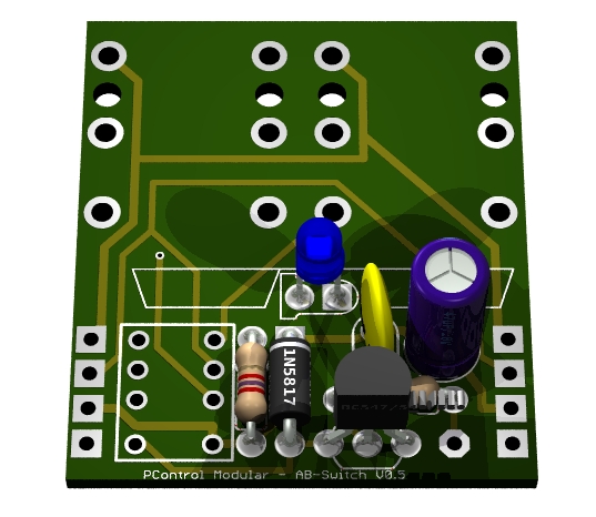
Provies Jacks that go to different Amps. The signal will be routed to Amp 1 or Amp 2 depending on the control signal.
The order switcher:
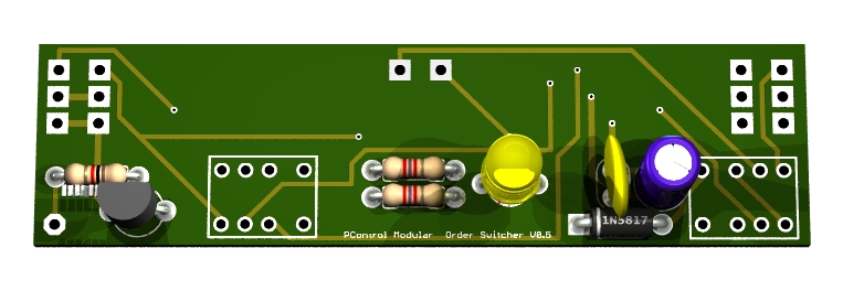
This add-on-board connects two loop boards together providing order switching. That means the signal can be routed like: in-signal->effectc1-->effect2->out or the other way round: in-signal->effect2->effect1->out.
The Out/Mute module:
Last switching module but very important. It provides the Out-Jack and (at the backside of the board) the mute switch which allows you to switch your signal as quiet as possible.
This gives you full control on your signal chain.
To build a stereo setup you just use two boards each and control the left and right channel using the same switching signal.
Also you see that each module has its own LED indicator. Depending on the display module you choose – or not choose- its use is optional or required.
I need to program it now!
Ok, here is a look at a display module that might be used in a 19″ rack unit as it also has space for board mounted tactile switches:
19″ Rack control&display module:
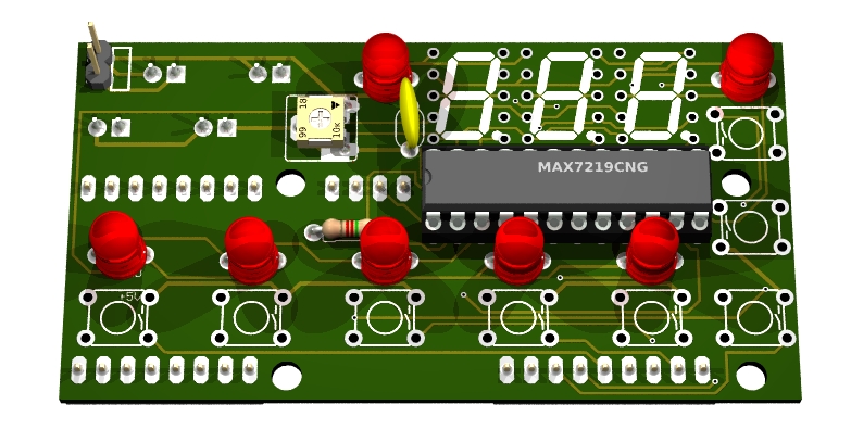
This module can carry the main unit on its backside as a piggyback module.
Alternatively you can use the following module as a simple indication/switching board.
Basic Indicator/Switch module:
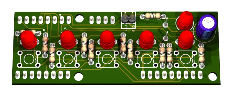
Even the basic module can be mounted piggyback onto the main control module or the
Five Loops Extension board:
If you need more than five loops you just add up to three extension boards(making a total of 20! loops)
The extension board has connectors on both sides which connect to another extension module or the main control unit.
No, it does not really have two connectors on the left-hand side. If you dont mount it to the display module you can cut it at the indicted line and get the same functionality on a smaller board. This might come handy if you want to wire all your switches and indicators at your most preferred positions in the enclosure.
The OLED display module:
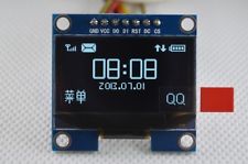
I also plan to have a small OLED display unit available to provide up-to-date technology in a very small size helping you to get the most out of this project. Currently waiting for the sample unit to come in.
11/25/2014 Current status: Initial desgn is finished. Shortly i will order prototype boards.
11/27/2014 Forgot to add a switching board:
Amp Switching Board:
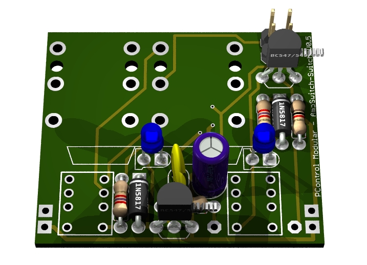
This module allows you to switch your Amp channels like with a foot switch. The board can simulate two switches – for example Clean/Crunch and Reverb – either using two mono jacks or a stereo jack. Please check your amps manual…
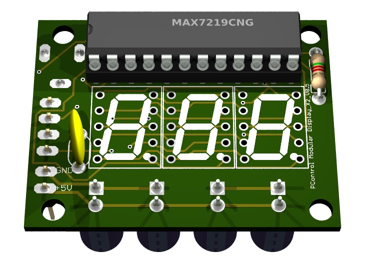
Also another display module has been designed which can be used on a 19″ 1HE panel or in your favourite enclosure as it features a very small form factor.
Small LED display module:
12/01/2014 designed the last board.
All eleven! boards have been reviewed and are ready for prototype-production.
Chips have been ordered for the prototype builds.
Power Supply Board:

… to be continued …